


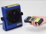
- Static eliminator that allows the selection of area intended for static neutralization
- Locking mechanism maintains angle of eliminator unit
- Error output signal function is useful to incorporate the unit into line applications
日本HAKKO静电测试器,HAKKO静电测试仪,HAKKO静电产生棒,HAKKO静电测量计等产品中国代理商
¥价格面议
浏览次数:1465次
- 产品规格:全系列产品
- 发货地:上海市徐汇区徐家汇街道
关键词
日本HAKKO代理商,日本HAKKO总代理,日本HAKKO静电测试仪,日本HAKKO静电测试棒,HAKKO静电测试仪,HAKKO静电测量计
详细说明

-

-

-

-

-


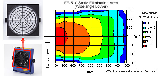
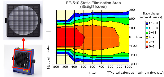
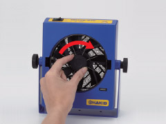
Choice of two louvers lets you select static elimination area.
Louvers snap on and off for easy handling. Safe design ensures unit cannot be turned on unless louver is attached correctly.
Wide-angle louver
Straight louver
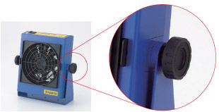
Locking mechanism maintains angle of eliminator unit
If you've ever found that a static eliminator wasn't working because vibration had shaken it out of alignment, you'll appreciate the FE-510's handy locking mechanism, which eliminates misalignment problems caused by vibrating equipment.
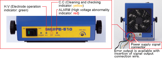
Error output signal is useful in built-in applications. This feature can be used to warn the operator when the discharge electrode is dirty or worn.
When used on a desktop, these warnings are provided by indicators.
Superb ease of maintenance
Discharge electrode can be replaced simply by turning it gently in a clockwise direction.

Choice of two louvers lets you select static elimination area.
Louvers snap on and off for easy handling. Safe design ensures unit cannot be turned on unless louver is attached correctly.
Wide-angle louver
Straight louver
Locking mechanism maintains angle of eliminator unit
If you've ever found that a static eliminator wasn't working because vibration had shaken it out of alignment, you'll appreciate the FE-510's handy locking mechanism, which eliminates misalignment problems caused by vibrating equipment.
Error output signal is useful in built-in applications. This feature can be used to warn the operator when the discharge electrode is dirty or worn.
When used on a desktop, these warnings are provided by indicators.
Superb ease of maintenance
Discharge electrode can be replaced simply by turning it gently in a clockwise direction.
|
|

| Can be used any where to quickly and easily check a variety of grounding systems. | |
|
|
Ensures employee safety. |
|
|
Eliminates product defects caused by static electricity. |

|

| Tester for antistatic shoes | |
|
|
Both shoes and the human body can be simultaneously tested for static charge |
|
|
The judgment based on JIST8103-specified standard values is indicated with a lamp and electronic sound |
| HAKKO 441B enables to control shoe wear, dirt and service conditions by classifying the JIS T8103 standard range into the following three levels: |
| Indication | Resistance Range* (Ω) | Status | |
| 108 Ωmode | 109 Ωmode | ||
| I | 1 x 10⁵ to 1 x 10⁶ | 1 x 10⁵ to 1 x 10⁶ | Sole is worn out. |
| II | 1 x 10⁶ to 1 x 10⁷ | 1 x 10⁶ to 1 x 10⁷ | Good |
| III | 1 x 10⁷ to 1 x 10⁸ | 1 x 10⁷ to 1 x 10⁹ | Sole is dirty. |
| *Reference value |
|
|
The judging criterion is selectable from two modes: 1×10⁸Ω or 1×10⁹Ω (with the selector switch) |
| Judgment | Resistance Range (Ω) | Indicator | Buzzer | |
| 108Ωmode | 109Ωmode | |||
| LOW | R < 1 x 10⁵ | R < 1 x 10⁵ | Red lamp | OFF |
| GOOD | 1 x 10⁵ >= R >=1 x 10⁸ | 1 x 10⁵ >= R >=1 x 10⁹ | Green lamp | ON |
| HIGH | 1 x 10⁸ < R | 1 x 10⁹ < R | Red lamp | OFF |

|

|
| HAKKO 441B is easy to use. Put on antistatic shoes, stand on the test plate, and press the pad. The main unit can be placed on a table or mounted on a wall surface with the accessory mounting base. | |


|
If any of the above conditions don't apply to the case, the product is broken. Please return it to where you bought it for repair. |
| One tester for all your soldering iron maintenance needs. | |||||||
|
|
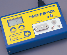
What should you check when doing a daily inspection of your soldering iron? Grounded soldering irons are maintained by inspecting leak voltage, tip-to ground resistance, and tip temperature. Grounded soldering irons cannot be maintained by checking insulation resistance. This method was used in the past in order to find out the level of leak current. Leak current is the current that leaks from the tip to a board or device. Leak voltage is a specific measurement of the level of this current. The leakage can adversely affect delicate devices, so it is necessary to check leak voltage on a daily basis. 
Most leak current flows from the tip via the ground wire to the outlet ground terminal, and is prevented from affecting the device. Because of this, tip-to-ground resistance is another important issue that must be checked daily. 
As the tip, element cover and other parts oxidize, heat conduction deteriorates and the tip temperature becomes lower. This causes the difficulty of soldering. Therefore, tip temperature should be inspected daily to have better soldering. |
||||||
|
|
Maximun current value mesured with HAKKO FG-101
|
||||||
|
|
In addition to traditional features, the FG-101 comes with two new functions: MAX HOLD and AUTO ZERO.
|
||||||
|
|
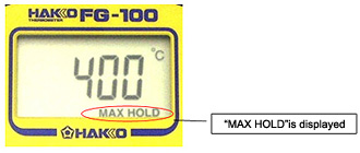
 When the MAX HOLD function is on, the maximum temperature is constantly displayed on the LCD. When the MAX HOLD function is on, the maximum temperature is constantly displayed on the LCD.If the MAX HOLD button is pressed for a short time (less than 1 second) the maximum temperature is updated. If the button is pressed for a long time (1 second or longer) the MAX HOLD function turns off. |
|
|
The zero point error of measuring instruments can be corrected by simply pressing the AUTO ZERO button and waiting for the display to return to normal.
|
|
Do not blow hot air (for example, with the HAKKO FR-802, etc.) directly onto the HAKKO FG-101 to measure the temperature.
If the hot air is blown directly onto the tester, the main unit of HAKKO FG-101 itself will be damaged. Please use the temperature probe for Hot Air Rework System 
When using the HAKKO FG-101, plug it into the outlet with a grounding terminal.
The HAKKO FG-101 cannot measure the leak voltage and tip to ground resistance of a soldering iron which has no grounding pin.
It can measure the leak voltage and tip to ground resistance of a soldering iron which has a plug with grounding pin. |

|
For the precise temperature measurement, place the tip on the measuring point on sensor horizontally. In general, the optimal temperature range for soldering is 300°C to 500°C, and that for SMD rework system is 300°C to 600°C. The tolerance of ±3°C within the optimal temperature range (300°C to 600°C) is assured. For the temperature range other than the above, the tolerance is not guaranteed but usually stays in the range of about ±5°C. |
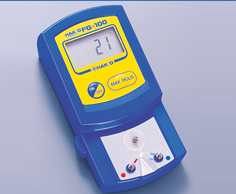
| Surely and easily Temperature control | |
|
|
Suitable for Lead-Free Solder · Good temperature response using a fine CA wire sensor (φ0.2mm) · Disposable sensor always maintains accurate temperature measurment · Sensor has the twice service life than conventional ones. |
|
|
Dimensional Measurement · Allows you to measure from any desired direction according to tip shape |
 *Design image only *Design image only
|
|
|
|
Auto Shut-Off Function · If no measurement operation is performed within 3 minutes, the power will be automatically shut off. |
|
|
MAX HOLD Function · When the button "MAX HOLD" is pressed, "MAX HOLD" will be displayed and the highest temperature of Iron will be held in the display. |
|
|
|
|
Easy-to-read temperature · Large and clear display · Digital temperature display make to read it accurately |
|
|
Compact Size · Convenient to carry and saves your workspace |
|
It is not necessary to deduct the room temperature that was displayed when the power was turned ON from the measured temprature. The temperature appearing on the LED display is the actual measured value. In general, the optimal temperature range for soldering is 300°C to 500°C, and that for SMD rework system is 300°C to 600°C. The tolerance of ±3°C within the optimal temperature range (300°C to 600°C) is assured. For the temperature range other than the above, the tolerance is not guaranteed but usually stays in the range of about ±5°C. |

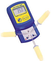
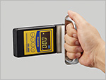
| Portable Static Level Meter, easily measured anywhere with Rotating Sensor Head. | |||||||
|
|
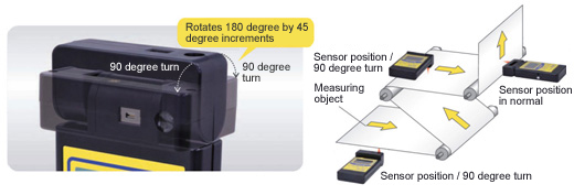
Rotating Sensor Head enables you to read the measurement value easily at any pointing angle. | ||||||
| ? Rotates 180 degree by 45 degree increments | |||||||
|
|||||||
|
|
Two modes for measuring electric potential: | ||||||
| ? Electric Potential Measurement | |||||||
|
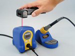
Momentary and peak value of static electric potential. Human body static electric potential, which can be measured hard in general, can be easily measured with Option Charging Level Measurement Plate for Body attached to the unit. |
|||||||
| * Measurement for the charged object. | |||||||
| * Measurement value can be hold temporarily by pressing Hold Button. | |||||||
| ? Ion Balance Measurement for Ionization Equipment HAKKO FE-510 etc. | |||||||
|
* Ion balance of the object cannot be measured.
|
|||||||
|
|||||||
|
|
The unit of measurement value on display is ‘kV’. | ||||||
|
If the result of measurement is 10V, the value on display shows ‘0.01kV’ in case of static electric potential. If the result of measurement is 1V, the value on display shows ‘0.001kV’ in case of ion balance. |
|||||||
|
|
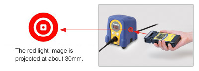
The distance between the sensor and the charged object should be 30mm. | ||||||
| Easily adjusts the distance by Red LED mark pointing at the charged object. | |||||||
|
|||||||
|
|
Adjusts Zero Point easily with just a single touch of a button. | ||||||
|
|
Battery indicator informs you the replacement timing of battery. | ||||||
|
When the battery charge icon shows one unit left on display, replace the battery.
|
|||||||
m.jevons1101.b2b168.com
 1017894018